| Note: This tutorial has been written and tested on Ubuntu 14.04 with ROS Indigo. |
| |
Extrinsic calibration of the David SLS-2 mounted on a robot
Description: This tutorial shows how to perform the extrinsic calibration of a David SLS-2 3D sensor on an industrial Fanuc robot.Tutorial Level: INTERMEDIATE
Description
This tutorial is a step by step guide on how to calibrate a David SLS-2 sensor mounted on a Fanuc robot. It aims beginners willing to perform the extrinsic calibration of 3D sensors; everything you will learn applies to other sensors/robots.
Motivation
Performing the extrinsic calibration allows you to know precisely where the sensor is in regards to the robot, in other words with a calibrated sensor the point clouds fetched are aligned in the robot frame. In practice this means that if you scan a cube, extract the corner coordinates of one edge of the box and feed the robot these poses, the robot will move along the edge.
This procedure is called "extrinsic calibration" "hand-eye" calibration; you should not call it "calibration" as it is confusing with the intrinsic calibration.
Hardware requirements
The hardware requirements varies depending on which sensor you use, with the David SLS-2 you will need an extra computer running Windows that you may not need using other sensors!
1x Fanuc industrial robot with ROS installed/running fanuc/Tutorials
- 1x David SLS-2 sensor with the David SDK software
- 1x sensor to robot mechanical interface
- 1x computer with Windows
- 1x computer with Linux / ROS installed
- An Ethernet network (the robot and the two computers on the same network)
Software requirements
- The David SDK software running on the Windows side
ROS on the Linux computer with industrial_extrinsic_cal requirements installed
Preparing the extrinsic calibration
Before going on the robot and actually performing the extrinsic calibration you need to prepare a catkin work-space with the necessary packages.
This tutorial has been written for Fanuc robots and a David SLS-2 sensor but most of it will apply to other robots brands supported in ROS Industrial and other sensors as long as you have a driver.
Packages you need
- A ROS package defining the sensor geometries (URDF/launch) and a package with a node to publishe images of your sensor (you could make this in only one package)
- A robot package and the corresponding driver
- A description of your robot using the mutable joint state publisher, with the sensor mounted
- A ressource package containing the extrinsic calibration trajectory, target definition etc.
- The industrial calibration package
In this tutorial we use a Fanuc robot and a David SLS-2 sensor:
fanuc contains the driver and some robot definitions
fanuc_experimental contains extra robot definitions (we will be using the M-900iB/700)
industrial_extrinsic_cal contains the code, service etc. for the extrinsic calibration
institut_maupertuis_robots_descriptions contains a definition of the M-900iB/700 with the mutable joint state publisher. It also contains the definition of the SLS-2 sensor and an image publisher.
Creating the sensor package
You need to create the sensor definition and also a node that will publish the sensor images on a ROS topic.
SLS-2 publishers contains the code of a ROS node that publishes images on a topic. It also contains a launch file to facilitate the configuration (IP address of the David SDK server etc.)
SLS-2 description contains URDF and launch files to define the SLS-2.
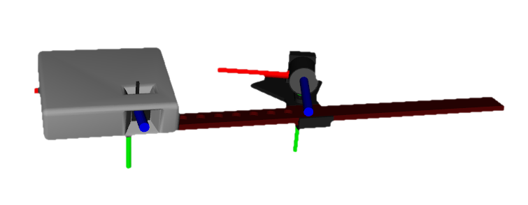
In the sensor definition you have to make sure that the axis have the right orientation like shown on the picture below (the camera frame is very important, the projector is not important):

You can test this definition with
roslaunch sls_2_description test_sls_2.launch
Note that the distance/angle between the projector and the camera can be modified when tweaking the red ruler. You must use values close the reality when including the sls_2.xacro file in your robot definition (see next chapter).
Creating the robot package
You need to take special care of the robot package. Here is a description of the packages inside the fanuc_m900ib_vision sub-directory:
fanuc_m900ib_sls_2_vision_moveit_config is a MoveIt config package for fanuc_m900ib_sls_2_vision_support
fanuc_m900ib_sls_2_vision_resources contains a simple program to test the extrinsic calibration, launch files that are necessary for the extrinsic calibration and yaml files that defines the extrinsic calibration target geometry etc.
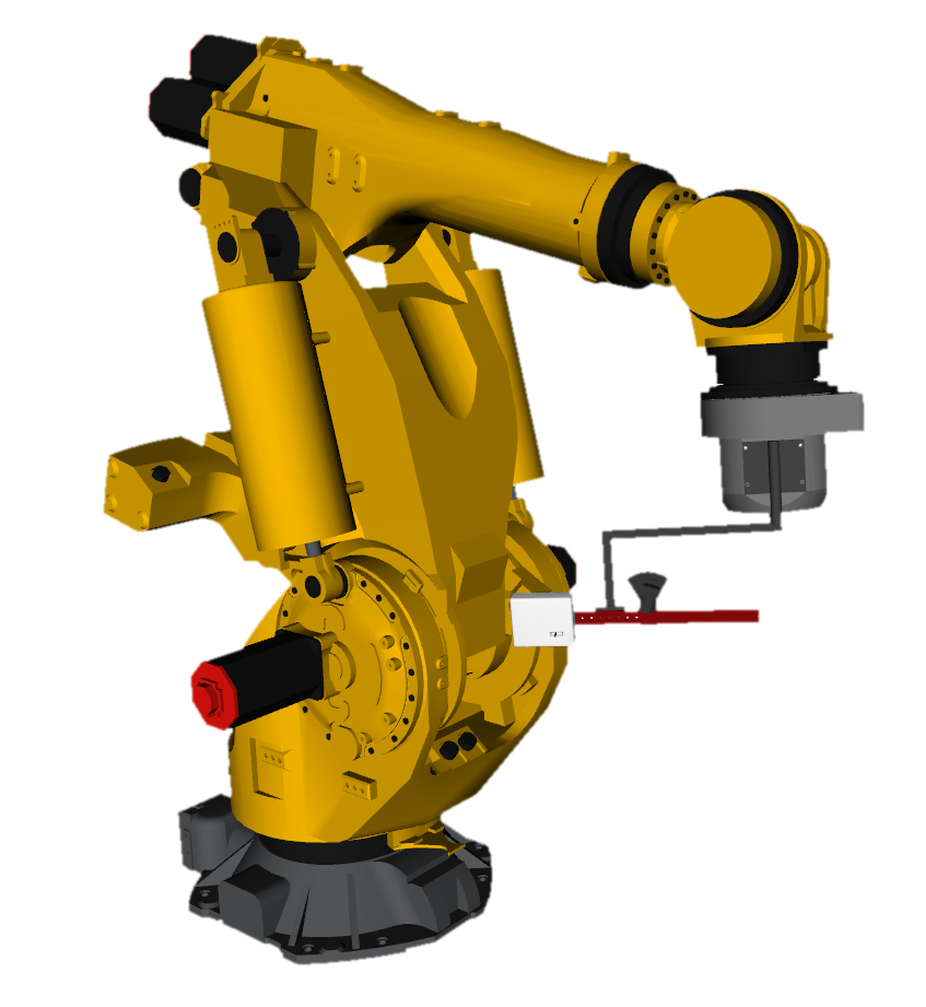
fanuc_m900ib_sls_2_vision_support contains a description of the M-900iB/700 robot with the vision_effector_description and vision_workcell_description attached to it.
vision_effector_description contains a description of our end-effector (without the sensor)
vision_workcell_description contains a description of the robot environment
To test the robot package use:
roslaunch fanuc_m900ib_sls_2_vision_support test_m900ib_vision.launch

The robot description includes de SLS-2 sensor with the right camera to projector distance/angle: m900ib_vision_macro.xacro.
You will notice that the robot has more than 6 axis, this is the mutable joint state publisher; it adds a series of transformation between the tool0 of the robot and the sls_2_frame. It also adds a series of transformation between the robot base and the target_frame; which represents the target the camera will observe to perform the extrinsic calibration.
This is done in the URDF of the robot:
A macro in the industrial_extrinsic_cal creates 6 transforms (3 translations, 3 rotations) between the two frames. These 6 transformations allows to move the child link.
These values are loaded from the mutable_joint_states.yaml files in the fanuc_m900ib_sls_2_vision_resources package.
In each of the launch files using this robot you must launch the mutable_joint_state_publisher and provide the YAML file path as argument like in the test_m900ib_vision.launch file.
- When the extrinsic calibration is complete these values are updated to the real/computed values.
The fanuc_m900ib_sls_2_vision_moveit_config package should be generated with the MoveIt setup assistant of your robot has nothing particular, just make sure to create at least two kinematic groups
A chain between base_link and tool0 (last link of the robot)
A chain between base_link and sls_2_camera, this one will facilitate your work if you want to automate the trajectory generation for the extrinsic calibration.
Adjusting the mutable joint states
Before starting the extrinsic calibration you must give an approximation value for each of the joint state publisher:
- For the camera frame
- For the target frame
This maximize the chances of the optimization algorithm of the industrial_extrinsic_cal to find correct values. If you do not set these values correctly the optimization algorithm might fail or worse, give a wrong answer.
To adjust the joint values launch the test file (test_m900ib_vision.launch) of the robot support package and use the following commands to tweak the joint states:
To get a list of the joints of your robot:
rostopic echo /joint_states
To get a mutable joint state value:
rosservice call /get_mutable_joint_states "joint_names:
- 'sls_2_frame_yaw_joint'"
To set a mutable joint state value:
rosservice call /set_mutable_joint_states "joint_names:
- 'sls_2_frame_yaw_joint'
joint_values:
- 1.5707"
Adjust the values of each of the 12 joints (6 for the camera, 6 for the target).
When you have found all 12 values that matches reality, copy them in the mutable_joint_states.yaml file.
Creating the ressource package
The ressource package contains:
launch files to check is the target can be located, start the calibration and store the results, test the extrinsic calibration, create a calibration trajectory.
- A node to test the extrinsic calibration (you don't have to create this, it is just a useful tool to see if the extrinsic calibration looks ok)
yaml files that define the extrinsic calibration job/trajectory, the target definition, the initial mutable joint states, the definition of the SLS-2 camera
The sls_2_camera_def.yaml defines the camera, focal length etc. Some of these values must be copied after performing the calibration of the sensor via the David SDK.
Perform the calibration of the sensor with the David SDK software : 

Then export the camera.cal and projector.cal from the David software and copy the values accordingly, in the sls_2_calibration.yaml. This is necessary because the David SLS-2 uses an specific frame when capturing point clouds. Copying these values makes sure we can reverse the transformation to get the point cloud in the camera frame (which we are going to calibrate).
You can use caljob_create.launch to create an extrinsic calibration job:
To capture a pose you need to set the ROS parameter /caljob_creator/capture_scene to true; rosparam set /caljob_creator/capture_scene true.
To quit creating the job and write the job file on the disk use rosparam set /caljob_creator/quit true.
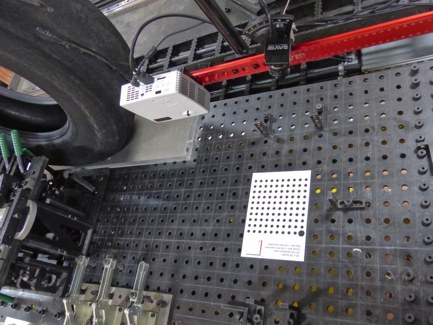
At the end the job should be written in caljob.yaml. Of course, when creating the job you must put a calibration target in front of your robot and make sure that the camera is able to locate the pattern for each pose (more info in the next item).

You can use target_locator.launch to test on each pose of the trajectory if the target can be located. If it is not, make sure that the image exposure is correct and that you are not too far/close from the target.
In the yaml directory you will find the calibration target definition and a corresponding SVG file ready for printing.
Performing the extrinsic calibration
- Make sure the SLS-2 is calibrated (with the David software)
- Make sure that the angle/distance of the real SLS-2 matches the simulated one
- Make sure you have up-to-date values in your mutable joint state files that matches reality
- Make sure the trajectory is collision free and each pose allows to locate the target. You should have at least 10 poses.
- Make sure the target definition matches the real one
- Make sure the printed target dimensions are correct
Before launching the calibration, start the robot and the driver, put the robot in auto mode and make sure ROS is able to communicate both with the robot and the sensor.
Launch the procedure:
roslaunch fanuc_r1000ia_sls_2_grinding_resources calibrate_sls_2_r1000ia_grinding.launch davidSDK_ip:=192.168.100.43 robot_ip:=192.168.100.200 sim:=false
In a second terminal:
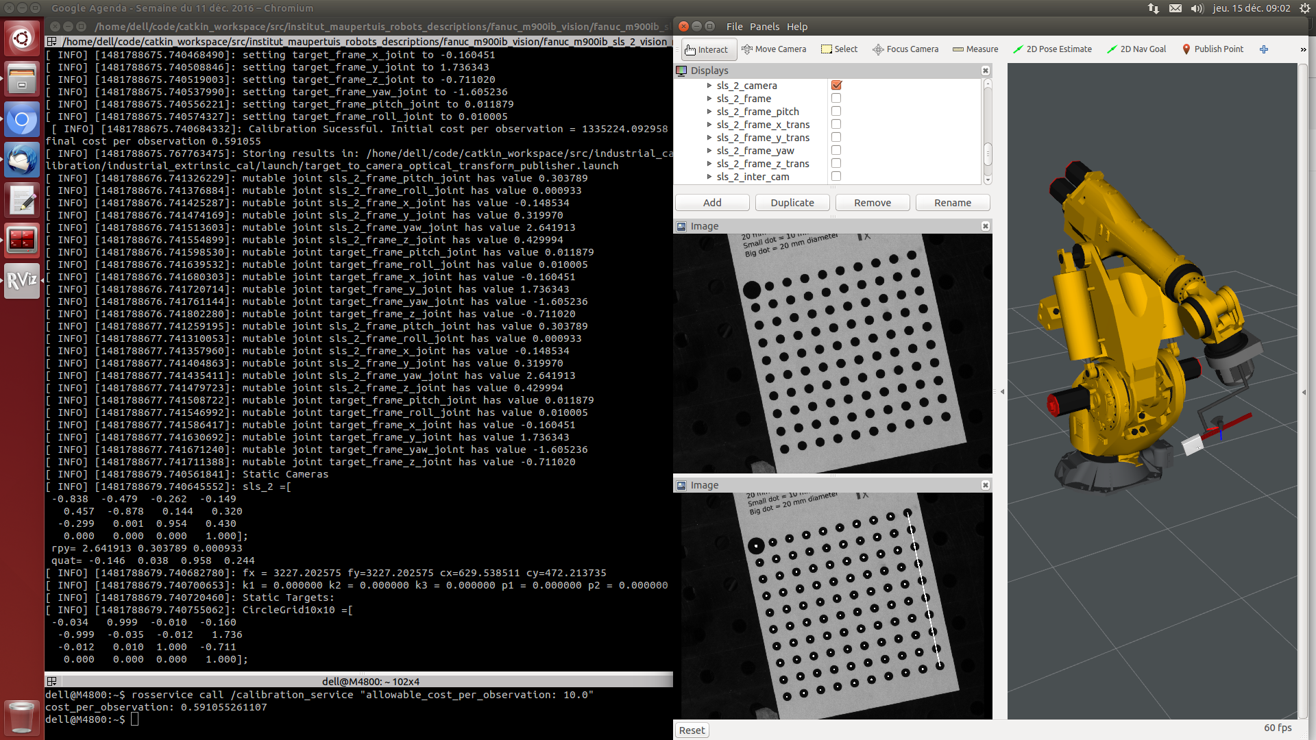
rosservice call /calibration_service "allowable_cost_per_observation: 2.0"
The robot will start moving around the target and the terminal display information about each pose capture.

At the end of the job, the mutable joint state publisher values are updated and you will see the sensor moving in RViz. If the orientation or translation of the sensor dramatically changed then something is wrong either with your initial mutable joint states values or with the extrinsic calibration results.
The new mutable joint states values are copied in the terminal and a new file is created in the yaml directory. However it is your job to update the values with the new one (if they are satisfying.
Troubleshooting:
- Make sure all poses leaded to a target being detected
- Make sure to have at least 10 successful targets captured
- Make sure the robot stopped at least 1 sec before capturing the image (the robot might vibrate)
- Make sure the sensor settings have not changed (perform a calibration with the David SDK software and copy the values again if not sure)


